Electrical supply · Film 19 of 35 · 0:49
Approved design to energization
Keep ratings, interfaces, documents, inspection and commissioning aligned with the approved design.
 METRO POWERCore Electrical SupplyPlan a project ↗
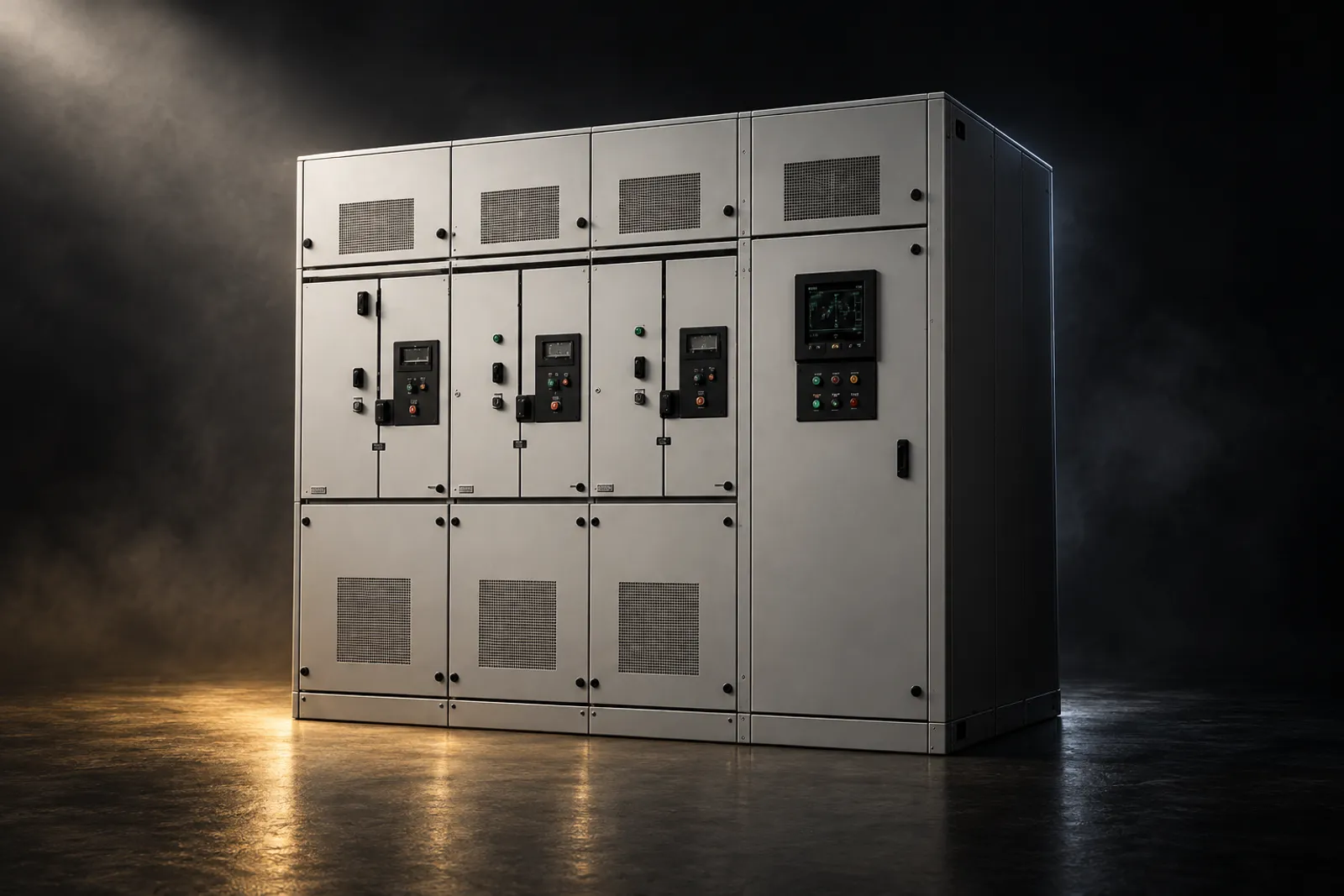
Core Electrical Supply
Metering accessories, instrument transformers, distribution equipment and substation-support hardware coordinated to the approved project requirement.

Understand the system
Core electrical supply covers the equipment that connects, protects, transforms and houses utility and customer electrical systems. Product selection must follow ratings, system studies, utility standards, installation conditions, approved drawings and the controlling bill of quantities.
Ratings, interfaces, protection, documents and delivery sequence have to agree before any item is released.
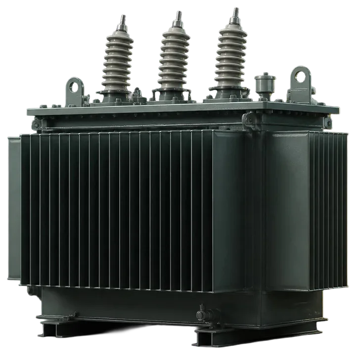
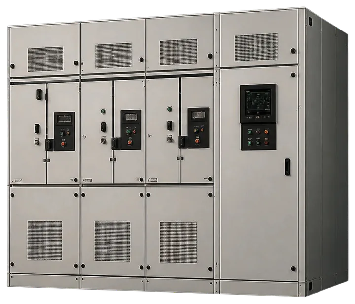
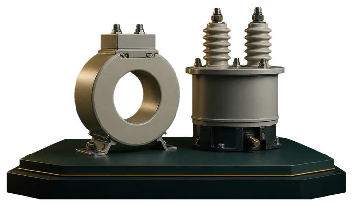
Product photographs on an original system drawing / Not a project installation
From drawing to site
The single line shows what each item must do in the system. The steps beneath it show how the item reaches site in the approved configuration: submittal, production, factory tests, packing, transport, receiving and preservation. Each step rests on the record of the one before.
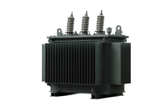 Distribution transformer
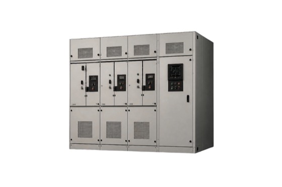 Switchgear bus
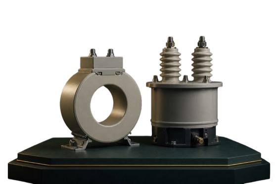 CT + relay
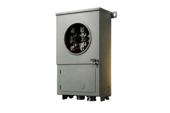 Metering
Equipment under control · representative single line
Specific inspection and preservation requirements depend on equipment, contract and manufacturer instructions.
Study delivery and installation in the AcademyCORE ELECTRICAL VALUE · TWO PERSPECTIVES
Electrical supply creates project value when ratings, interfaces, documentation and delivery sequence remain tied to the approved design and actual site conditions.
01FOR THE PROJECT, ENGINEERING OR SITE TEAM
Ratings and duties can be checked against the controlled single-line, load data and specification.
What makes it trueRequires approved design inputs and disciplined revision control.Accessories, protection, terminations and equipment boundaries can be reviewed as one system.
What makes it trueRequires complete scope, drawings and responsibility boundaries.Drawings, tests, certificates and deviations can be closed before shipment or installation.
What makes it trueRequires named technical and commercial approval authority.Receiving and installation can be planned around site access, storage and construction priorities.
What makes it trueRequires a current schedule and accountable delivery plan.02FOR THE OWNER, OCCUPANT OR OPERATING TEAM
Equipment can be selected around actual load, environment and operating requirements.
What makes it trueSuitability depends on approved engineering and site verification.A controlled document and test package can support commissioning and future maintenance.
What makes it trueRequires complete closeout records and accepted test evidence.Early interface checks can surface mismatches before equipment reaches the installation point.
What makes it trueRequires coordination across design, procurement and site teams.Warranty, maintenance and operating ownership can be established before energization.
What makes it trueResponsibilities depend on the final contract and approved handover plan.System architecture
Follow the journey from physical equipment to the decision a customer or operator can act on.
The approved single-line and load establish system ratings and duty.
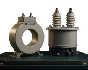
Transformers and instrument transformers adapt voltage and current for delivery, protection and measurement.
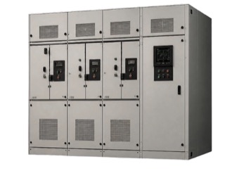
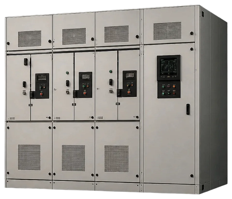
Switching, protection, conductors and enclosures control and contain electrical energy.
Inspection, testing, documentation and commissioning establish readiness for service.
Every item must fit the approved electrical design, interfaces and delivery sequence.
02RATED EQUIPMENTCONTROL POINT 1The approved single-line, specifications and bill of quantities are the controlling basis for compatible equipment supply.
Field realitybecomesOperational action
System to real world
Ratings come from approved design
Equipment arrives in installation sequence
Tests and handover establish service readiness
This visual explains system behavior. Final performance depends on approved design, field conditions, configuration and operating discipline.
Metro Power visual explainer
Use this short film as orientation, then continue into the system architecture, technical lesson or readiness action.
Keep ratings, interfaces, documents, inspection and commissioning aligned with the approved design.
The Metro Power solution
We close the gaps between the manufacturer’s product, Philippine site conditions and the people who must operate the system.
Metro Power closes the two gaps marked on the line.
Complete decision path
A solution is complete only when technical behavior, project evidence and operating ownership remain connected.
Single-line diagram (SLD), BOQ, specifications, studies and transmittal status
Technical schedules, drawings and responsibility matrix
Deviation closure, inspection and test plan (ITP), drawings and factory acceptance test (FAT) plan
Receiving, site acceptance test (SAT), settings, as-builts, training and spares
Failure modes to control
Compare ratings, interfaces, accessories, standards and exclusions.
Use an approval and revision register at every release gate.
Complete site, functional and integrated commissioning evidence.
Acceptance evidence
Possible equipment paths
These are starting points for discussion, not automatic recommendations. Use the plain-language clues below to understand where each option may fit and what Metro Power still needs to confirm.
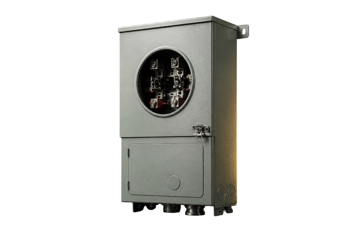
Project-configured
Evidence: Project details neededProduct reference image
Service equipment matched to meter form, conductor, sealing and installation conditions.
3 more Core Electrical Supply products
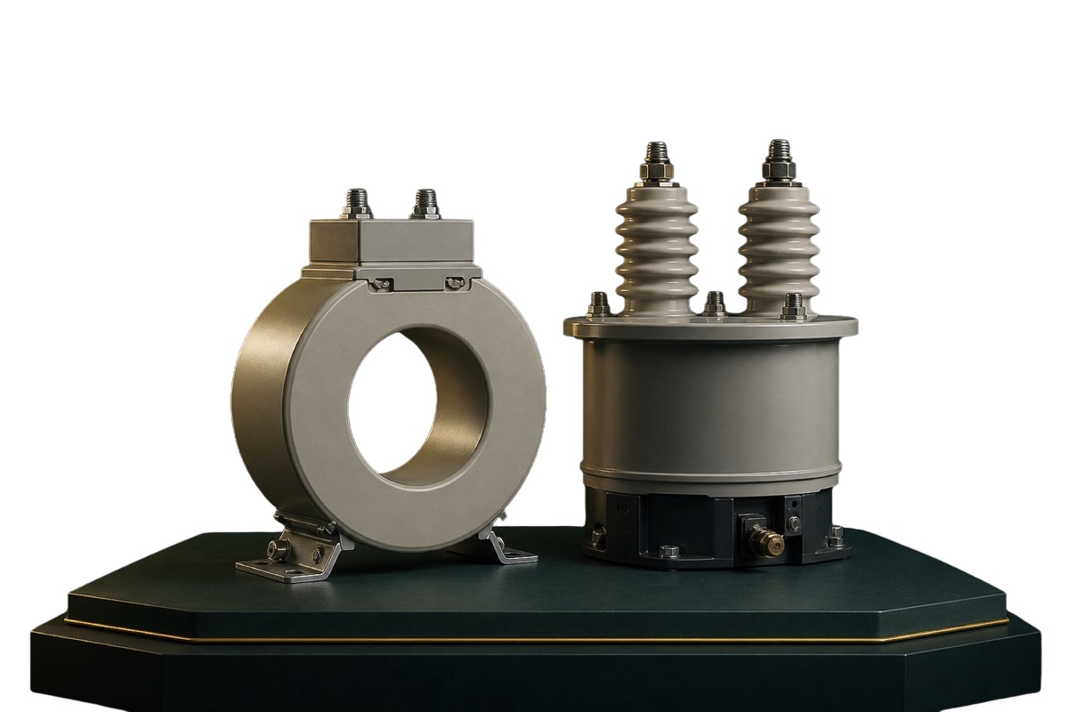
CT / PT applications
Evidence: Project details neededProduct reference image
Current transformer (CT) and potential transformer (PT) interfaces for measurement and protection, selected against ratio, burden, accuracy and insulation requirements.
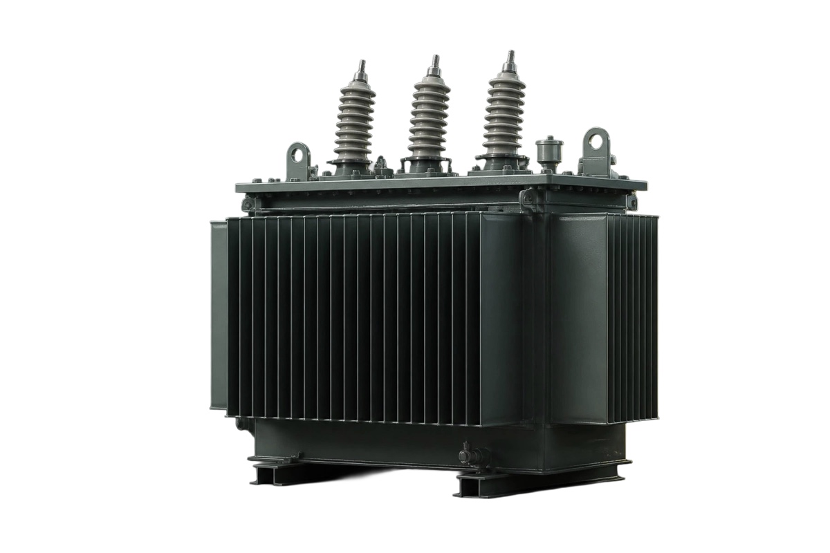
Project-configured
Evidence: Engineering review neededProduct reference image
Distribution transformers selected from validated load, voltage, vector group, impedance and installation data.
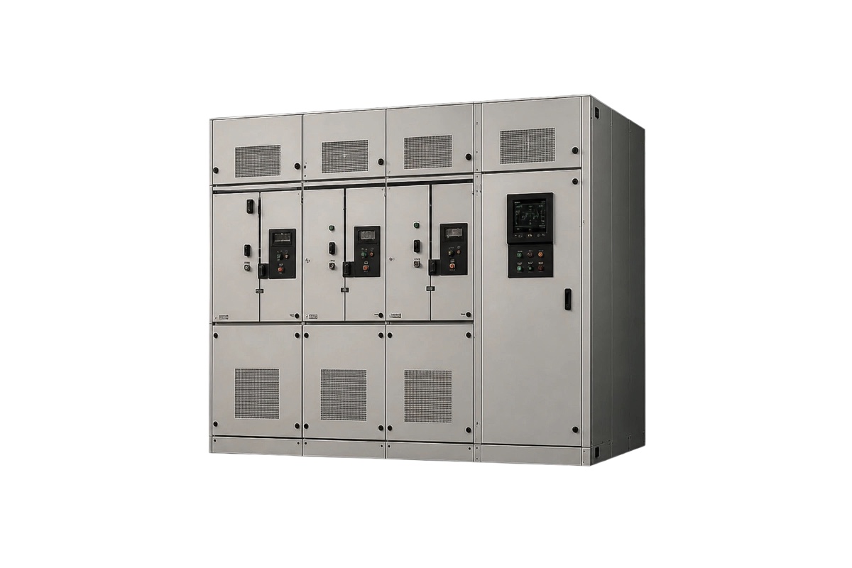
Project-configured
Evidence: Engineering review neededProduct reference image
Switching, protection and supporting equipment coordinated from approved design information.
Brands, ratings, standards, test requirements and supply scope are released only after review of the current approved project documents.
Turn learning into a decision
Move from a bill of quantities to equipment that is electrically correct, documented and sequenced for site delivery.
01Project owner
The approved design, project phase, schedule and acceptance responsibility define the supply outcome.
Confirm scope and interfaces02Engineering
Voltage, load, fault level, insulation, environment, protection and interfaces must come from controlled design data.
Submit approved drawings03Procurement
Control brands, standards, included accessories, tests, documents, exclusions and delivery terms.
Review the controlled BOQ04Site team
Sequence, access, receiving, storage, inspection, commissioning and closeout must be planned before dispatch.
Build the delivery planWhere it may fit
You do not need to choose equipment yet. If one of these situations sounds familiar, Metro Power can help define the correct starting point.
Prepare without the guesswork
These inputs help us understand the project. They are not entry requirements, and you do not need every item before contacting us.
The single-line diagram shows how equipment connects and which ratings and interfaces govern selection.
Voltage and fault level are fundamental safety and equipment-duty inputs.
Actual load and operating duty determine capacity, thermal performance and service expectations.
Ratings and standards define the technical boundaries for a responsible comparison.
Indoor, outdoor, heat, moisture, altitude, access and space can change the required construction.
The current document set and required sequence control scope, interfaces and delivery timing.
Your next decision
Ratings, interfaces, tests and delivery sequence come from controlled project information. Share the latest drawing or requirement you have, and Metro Power can identify the next check before a supply recommendation.